Summary
This project is actually the continuation of the previous project explained in the first blog however this time the project has been carried out using visual programming in Dynamo. The methodology used to create the solid mass has essentially been the same in a way that first of all a cuboid shaped mass was created. This mass was then cut from the corners to give us the desired shape of the building. This step was followed by the creation of communication rings and opening in the podium. Next, curtain panels were applied to the surface and their color was tied to the sun path. The creation of such curtain panels could not be achieved using typical techniques in Dynamo therefore new techniques were developed.
Explanation
1) Creation of Mass:
The following images explain the steps taken while modelling the mass in Dynamo. The nodes important to mention are:
Solid.By.Loft
Polygon.ByPoints
Curve.ExtrudeAsSolid
Solid.Difference
Curve.PointAtParameter
Surface.BySweep
Ellipse.ByOrigin.Radii
 |
| Inputs for form creation |
 |
| Creation of Cuboid |
 |
| Creation of Cuboid |
 |
| Cutting the cuboid at Corners using Solid.Difference Node |
 |
| Placing points on parapet for creation of communication rings |
 |
| Creating Rings using Surface.Sweep |
 |
| Creation of Circumscribed Rectangle |
 |
| Geometry of Podium's opening |
 |
| Opening of Podium using Solid.Difference |
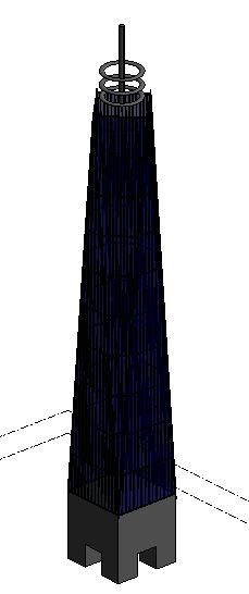
 |
| Final Mass created in Dynamo |
Application of Curtain Panels
Problem in Dynamo
Perhaps the most difficult part of this project was the application of curtain panels on the mass surface through Dynamo. Although the mass seems quite simple and one expects Dynamo to easily apply the curtain panels but in actual its quite the opposite. The commonly used node "Quad.Panel" which is available in the package "LunchBox" does not seem to work on triangular surfaces. In fact, Quad.Panel requires a quadrilateral surface to create panels. Moreover, the panels it creates on the quadrilateral surfaces are also not consistent in size in some cases.
Solution Approaches:
To address this limitation of Dynamo, two different approached were used. Although they are not perfect solutions but they do serve the purpose to greater extent. The approaches are:
1) Creating Curtain Panels within Curtain Panel
In this approach, a triangular panel is first created and a solid surface is formed inside the boundaries. This surface is then divided in U and V grids and another curtain panel of rectangular shape (formed in a separate massing environment and then uploaded into the working environment) is applied to the grid. The triangular panel resultantly created is then applied to the triangular face of the building using coordinates of the corners already available.
 |
| Rectangular panels within triangular panel |
 |
| Final Result of Application of Curtain Panel |
 |
| Final Result of Application of Curtain Panel |
|
 |
| Cloud rendering. As can be seen the rendering with such an approach is not very clear at all |
2) Manual creation of Panels
The second approach was to manually create curtain panels on the 8 surfaces of the mass. To achieve this purpose, the concept of unit vectors was used. As we already had the X,Y,Z coordinates of 3 corner points, unit vectors were derived using the unit vector formula. These vectors gave us a direction in which further points were created. Both Dynamo and Microsoft Excel were used in this regard. The coordinates of corner points were exported to Excel where the desired calculations were carried out to find the coordinates of other points according to our choice of grid. The coordinates were then imported back from Excel to Dynamo and converted into points. The figures below show the technique used for generation of points on surface
 |
| Unit vectors giving a sense of direction |
 |
| Points generated on perimeter using unit vectors |
 |
| Unit Vector for generating points inside the triangle |
 |
| Points generated inside triangle in layers from bottom to top |
 |
| A glimpse of Excel Calculations |
 |
| A glimpse of Excel Calculations |
|
Problems with Manual Creation of Curtain Panels:
At time when creation of points on the surface seemed like a breakthrough, formation of curtain panels from these points posed another serious problem. There was a need to group the points in numbers of 4 such that each point would represent the coordinates of the corners of panel . For first two panels the points had to be grouped in the order given below in figures:
 |
| Points required to be grouped for first panel |
 |
| Points required to be grouped for second panel |
|
In our case, neither were the points generated in this order nor was there any way to order them in this fashion using excel or Dynamo. The number of points in each layer from bottom to top kept changing with changing geometry of the mass. With such a variation, a logic could not be established to pick points in the order shown above. Such a logic might have been possible with Python or other high level languages but due to lack of time for project the idea of creating an ideal rectangular grid was dropped. However, because a curtain panel was necessary for the building, a simple triangular panel was chosen which would divide the whole face of the building into 4 smaller triangles. Due to less number of panels on each face, the points for these panels were ordered manually and fed into adaptivecomponents.byPoints node. This is how the paneling process was carried out at the end.
 |
| Panel Points for Simple Triangular Panels |
 |
| Simple Triangular Panels |
Coloring of Surface Using Sun Path
Apart from applying panels to the building's surface, the color of these surfaces can also be tied to the sun path. This is done by creating vectors normal to the surfaces and measuring the angle these vectors make with the sun. As the location of the sun changes, the angle between the normal vectors and sun change and thus the color of the surface. For color input, we either use RGB values or we upload a colorful image and extract the colors from it.
The nodes used in this process are:
Color.ByARGB
Color Range
SunSettings.SunDirection
Surface.NormalAtParameter
Surface.PointAtParameter
SunSettings.Current
Vector.Dot
 |
| Generation of Normal vectors and Getting Sun Data |
 |
| Selecting Color Range |
 |
| Applying Extracted color to surface |
 |
| Colorful Surface of the Building |
 |
| Sun Path effecting colors |
Video


Comments
Post a Comment