Midterm Project
This project is a part of ARCH 653: Building Information Modelling course offered at the Department of Architecture of Texas A&M University . The purpose of this project was to create a building model that can be controlled parametrically in different dimensions. The students were supposed to select a real world building and, prior to modelling, gather useful information about them like plans, elevations and most importantly the architect's design intent. The students were also given a free will to introduce their own design intent in the model.
For my project i selected "One World Trade Centre" as my target building. The details of the building are given below:
Tower Details
Podium
The tower rises from a podium whose square plan
measures approximately 204 feet by 204 feet, the same footprints as the
original towers. The podium is 186 feet tall and is clad in triple-laminated,
low-iron glass curtains and horizontal, embossed stainless steel slats. The
more than 4,000 glass curtains, each measuring approximately 13 feet by two
feet, are fixed and positioned at varying angles along the vertical axis to
form a regular pattern over the height of the podium. This pattern both
accommodates ventilation for the mechanical levels behind the podium wall and,
in combination with a reflective coating, refracts and transmits light to
create a dynamic, shimmering surface. The podium’s heavily reinforced concrete
walls serve as a well-disguised security barrier (Source: archdaily.com)
 |
Source:
archdaily.com
|
Tower
Above the podium, the tower’s square edges are chamfered
back, transforming the square into eight tall isosceles triangles. At its
middle, the tower forms an equilateral octagon in plan and then culminates in a
stainless-steel parapet whose plan is a 150-foot by 150-foot square, rotated 45
degrees from the base. The resulting crystalline form captures an ever-
evolving display of refracted light: the surfaces change throughout the day as
light and weather conditions shift and as the viewer moves around the tower.
Careful thought was also given to the design of the tower’s corners. Made of
embossed stainless steel, the eight edges recall the reflective corners of the
original twin towers. (Source: archdaily.com)
 |
| Source: archdaily.com |
Structure
One World Trade Center features a hybrid structure comprised
of a high-strength concrete core surrounded by a perimeter moment frame of
steel. Paired with the massive concrete shear walls of the core, the steel
frame adds rigidity and structural redundancy. Both bolted and welded together
for maximum connection strength, the steel members were hoisted into place by
two Manitowoc cranes – the largest ever used in New York City. The tower’s
tapered, aerodynamic form reduces exposure to wind loads while simultaneously
reducing the amount of structural steel needed. Rising a quarter mile into the
sky, the tower is brute strength veiled in glass. (Source: archdaily.com)
 |
| Source: archdaily.com |
 |
| Source: archdaily.com |
Tower Modelling
To model this building the following steps were followed chronologically:
1) Modelling of Conceptual Mass
2) Modelling of Custom facade and its application on conceptual mass
3) Uploading of updated mass to revit project and creation of mass floors in project
4) Creation of plan for one of the mass floors and concrete wall around podium
5) Creation of parkina around the building
Among the above mentioned steps, modelling of the conceptual mass was the most important and time consuming step as all of the parametric relations were influencing this mass.
The details of each of these steps are as follows:
1) Modelling of Conceptual Mass:
The modelling of conceptual mass was done in two phases:
a) Modelling of tower
b) Modelling of communication rings and beacon
a) Modelling of Tower
In this step, first a solid cuboidal mass was created with both top and bottom as squares with equal dimensions. The dimensions of these squares were kept equal to those of the building's podium. It is important to mention here that this mass was a combination of two separate masses. The first mass was that of the podium and second mass was that of the structure above podium. The podium's mass was formed between two rectangular sections both made of adaptive points placed at four corners. One at the upper level representing the top of podium and the other at ground level. The purpose of using adaptive components at the base was to have better control. An attempt was made initially by using simple model lines and reference points to serve this purpose but several complications aroused and many constraint issues were faced in later stages. The creation of solid mass was followed by cutting openings in for entry to the building. These were made in the building's podium using void masses however these masses were not controlled parametrically. At the end, concrete material was applied to the podium's mass resembling the actual structure.
 |
| Use of Adaptive Components to form base squares |
 |
| First mass created between rectangular sections |
 |
| Cutting of Voids for Opening |
 |
| Application of Material to Podium Mass |
 |
| Load of Material into library |
The mass for structure above podium was also created in a similar fashion. It was formed between two squares made of adaptive components. The bottom squares was the one used previously for podium's mass creation. The top square was newly created and was at the level of parapet (Level 3). It was identical in dimensions to the bottom square.
Overall, the two masses created formed a cuboid shape This cuboidal mass created was then cut by void forms at the corners to get the actual shape of the tower. To make this happen, it was necessary to create points which when joined by model lines would form a plane that would be turned into a void mass afterwards. These points also had to be controlled parametrically in a way that when the width of the building's parapet or podium would change, the points would change their position accordingly and resultantly change the void masses at the corners too. To achieve this complex goal, one more square was created at a level (Level 3) considered as the host of parapet. This square was circumscribed by the previous one which controlled the shape of cuboid. The circumscribed square was made of model lines drawn between reference points and represented the actual boundries of parapet. It is important to mention here that the size of circumscribing square (formed using adaptive points) was controlled using an equation* which relates the side length of circumscribing square (denoted as X in the project) to that of the circumscribed square. Whenever the width of circumscribed square changes, the width of circumscribing square changes accordingly OR whenever the solid cuboidal mass changes its shape, the void masses at the corners change accordingly thus maintaining the shape of the tower.
*Length of side of cicumscribing square(X)= sqrt(2) x Length of side of circumscribed square
 |
| Circumscribing and circumscribed squares at parapet level |
 |
| Cubidal mass made from combination of two separate masses |
 |
| Voids cutting through solid mass at the corners |
 |
| Final shape after cutting at corners |
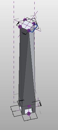
b) Modelling of communication rings and beacon
The second phase of conceptual mass involved the modelling of communication rings and beacon. As a first step, 4 reference planes were created parallel to the level considered as the host of parapet (Level 3). 3 of these planes were intended to host 3 communication rings whereas the 4th plane was intended to host the top of beacon. On each of these reference planes, a reference line was drawn which ran perpendicular to the reference plane already drawn on top of parapet. This gave us an intersection point on each of these planes from which rings could be drawn at a certain radius. First of all, the towers's beacon was formed from a solid extrusion which ran from parapet's surface to highest placed reference plane. This was followed by drawing of rings on 3 planes. After drawing the rings, several reference points were placed on these rings. Some of these reference points were used to form solid masses from the rings and some were used to draw the supports for these rings from the beacon. Apart from controlling the radius of these rings with parameters, their heights with respect to each other as well as parapet were also controlled through parameters. In this way a full control was achieved on communication rings and beacon through parameters.
 |
| Rings, beacon and their hosting planes |
At the end, solid masses were formed from these rings and a material with color resembling copper was applied to them. This material was newly created and its color was attained from an image found from internet.
 |
| Solid ring masses with material applied |
 |
| Making new material's color from loaded image |
2) Modelling of Custom facade and its application on conceptual mass
The facade of actual tower is rectangular in shape with the podium having narrower squares compared to rest of building above it. Using pattern based curtain panel family, two curtain panels were formed: One for the podium and one for rest of the building. The reason for using two curtain panels was to apply different curtain wall materials to them. The curtain panel intended for podium had clear glass as the curtain wall and the one intended for rest of the building had blue glass applied to it. The frame of the curtain panel was made from solid form and its material was set as aluminum.
 |
| Curtain panel with blue colored glass used for building above podium |
 |
| Curtain panel with clear reflective glass used for podium |
 |
| Blue glass material |
 |
| Panel frame material made of aluminum |
 |
| Clear glass material |
Before loading these two curtain panels the surfaces of the conceptual mass were divided into squares. Initially these squares were made in accordance with the actual size of curtain panels used in one world trade centre however, this resulted in a very fine mesh which was difficult for revit to render when curtain panles were applied to it. Therefore, the size of these squares was increased to 20ft x 60ft for mass above podium and 10ft x 60ft for podium's mass. After division of the surfaces, the two rectangular curtain panel families were uploaded into the conceptual mass family and applied to the appropriate divided surface.
 |
| Division of conceptual mass surface |
 |
| Application of curtain panel to conceptual mass |
3) Uploading of updated mass to revit project and creation of mass floors in project
The conceptual mass with custom facade applied to its surface was then uploaded into a project and different levels were created with spacing approximately resembling the floor spacing of actual building. The resemblance was approximate because of lack of data regarding the actual spacing between different floors. For the bottom 6 and top 9 floors, a spacing of 30ft between the levels was selected. For the rest of the floors in between, a spacing of 13ft was selected. After placing the levels with the desired spacing, mass floors were created at each level. 12 inch thick concrete was selected as the material for these mass floors. At the end, a roof was formed at the top of conceptual mass which too was a 12 inch thick concrete.
 |
| Creation of mass floors at different levels |
 |
| Elevation of mass model |
 |
| Elevation of Actual Structure (Source: archdaily.com) |
4) Creation of plan for one of the mass floors and concrete wall around podium
Keeping the scope of project in mind, only one floor was modeled which was the floor located right above the podium. In actual tower this floor contains Mechanical, Electrical and Telecom rooms along with a service vestibule, elevator lobby, tower egress stairs, office space area and restrooms. In our project not all of these elements were modeled due to complexity of floor plan, time constraint and lack of detailed information about the floor plan. As a result, focus was put mainly on modeling the mechanical room and elevator lobby. Some families like Elevator (Source: https://www.revitcity.com) and Fuel Standby Generator (Source: https://www.bimobject.com) were downloaded from internet due to their unavailability in default revit families. The rest of items like doors, windows and wall lamps etc. were all taken from default revit libraries.
 |
| Floor Plan for Actual Structure (Source: archdaily.com) |
 |
| Floor plan of model |
Beside the plan, a reinforced concrete wall was also created around podium which was hosted by the ground level. This concrete wall was in accordance with the actual building which has a heavily reinforced concrete wall bounding the podium and a curtain wall around this concrete wall. As this wall blocked the openings of the building previously created, a cut was made in the wall through the cut tool equal in size to the previous opening.
 |
| Concrete wall cladded by curtain wall at ground level |
5) Creation of parking around the building
After modeling of the floor, attempt was made to model the environment around the building. Due to lack of time, only a parking space was provided around the building with parking lots on both sides. The functions in "massing and site" tab were used to achieve this purpose.
 |
| Parking lots around model |
Other Project Deliverables:
Rendering 1
 |
| Exterior Rendering of Model |
 |
| Interior Rendering of Mechanical room |
Screen Shot 1

Screen Shot 2

Screen Shot 3

Screen Shot 4

Note: X represents the length of side of circumscribing square
Movie

Comments
Post a Comment